
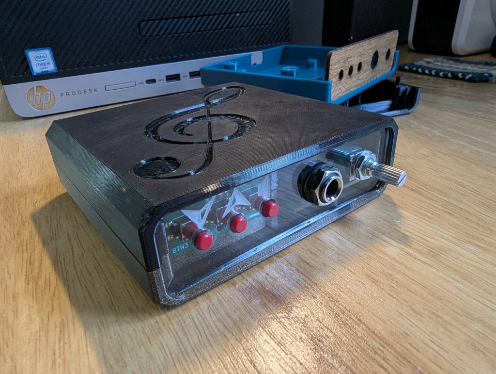
My local maker space is putting together a circuit board building class, and I was asked to design a case for it. I decided to use tools readily available at the space (3D printer(s), laser cutter) and produce design files that would be easily to personalize with ones own images and engravings. This project was my first test-drive of FreeCAD 1.1, and I was very pleased with all the features and fixes. My geometry is derived from the imported circuit board CAD, which used to mean that FreeCAD would have difficulty keeping things in order once the models became more than a few operations long, but this project went pleasantly smoothly. While I did have to do a bit of fixing when I made major changes halfway down the timeline, I was generally happy with the workflow and the result.
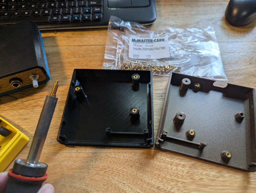
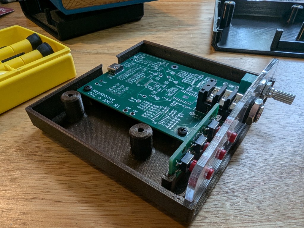
In the spirit of design for assembly, I tried to make it so that parts could be installed one at a time without having to hold multiple loose doohickeys together at once – the hope was that they’d come together before you drop some part of it and have to start over. Heated inserts made it so that screws could be installed and removed from the case as many times as the builder wished, and a case that can be printed without supports lowered the difficulty of creating a new one if the need arose.
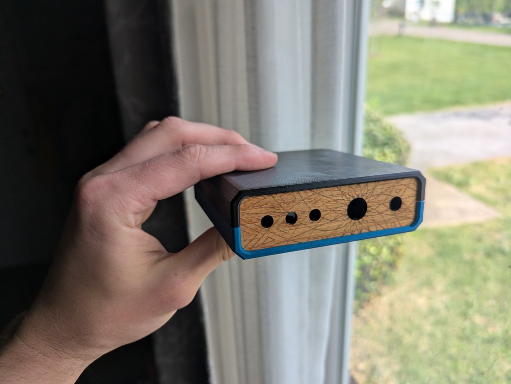
Since 3 mm acrylic and plywood are both available in the laser cutting zone of the maker space, I used that as the basis for the front panel. I provided a file that has just the hole cutouts in case anyone wished to customize it with their own engravings.
I’ll probably iterate on the design once or twice more before the class goes live to improve the fit and finish of the case even more, but overall I’m happy with how this turned out.

Leave a comment