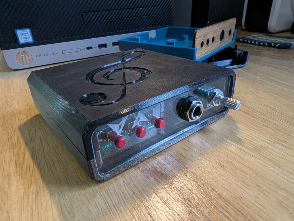
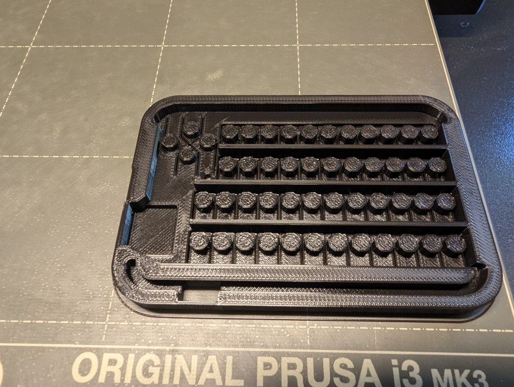
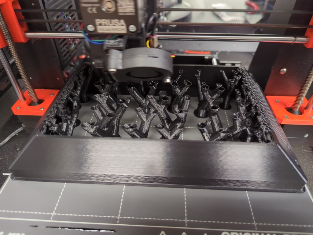
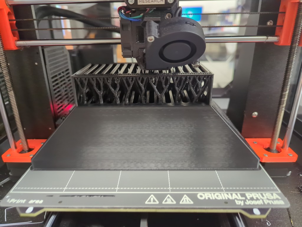
My local maker space is putting together a circuit board building class, and I was asked to design a case for it. I decided to use tools readily available at the space (3D printer(s), laser cutter) and produce design files that would be easily to personalize with ones own images and engravings. This project was my first test-drive of FreeCAD 1.1, and I was very pleased with all the features and fixes. My geometry is derived from the imported circuit board CAD, which used to mean that FreeCAD would have difficulty keeping things in order once the models became more than a few operations long, but this project went pleasantly smoothly. While I did have to do a bit of fixing when I made major changes halfway down the timeline, I was generally happy with the workflow and the result.
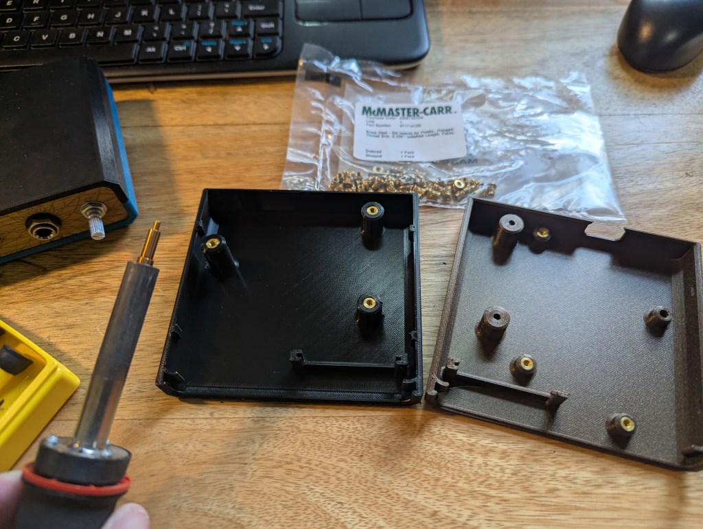
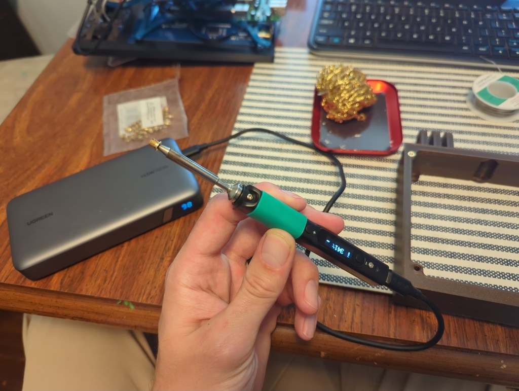
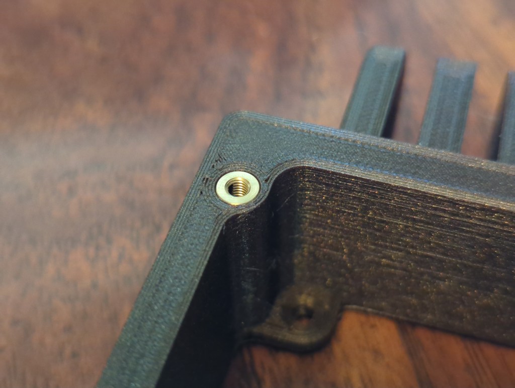
In the spirit of design for assembly, I tried to make it so that parts could be installed one at a time without having to hold multiple loose doohickeys together at once – the hope was that they’d come together before you drop some part of it and have to start over. Heated inserts made it so that screws could be installed and removed from the case as many times as the builder wished, and a case that can be printed without supports lowered the difficulty of creating a new one if the need arose.
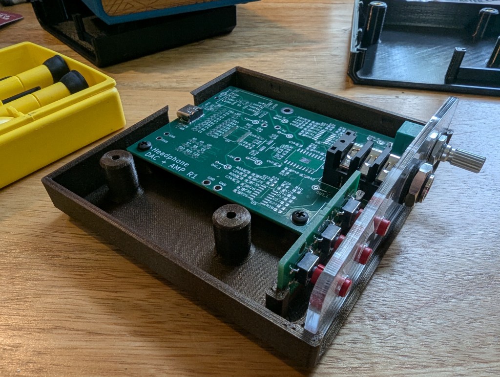
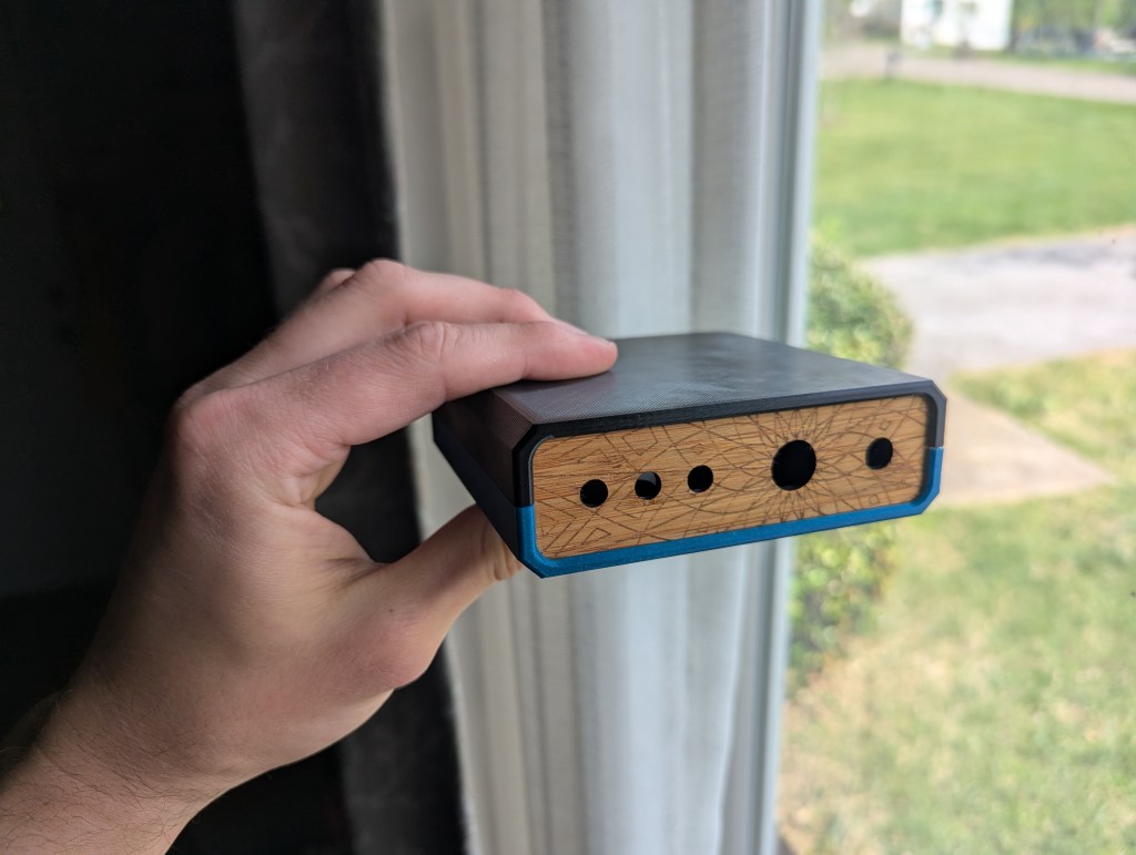
Since 3 mm acrylic and plywood are both available in the laser cutting zone of the maker space, I used that as the basis for the front panel. I provided a file that has just the hole cutouts in case anyone wished to customize it with their own engravings.
I’ll probably iterate on the design once or twice more before the class goes live to improve the fit and finish of the case even more, but overall I’m happy with how this turned out.
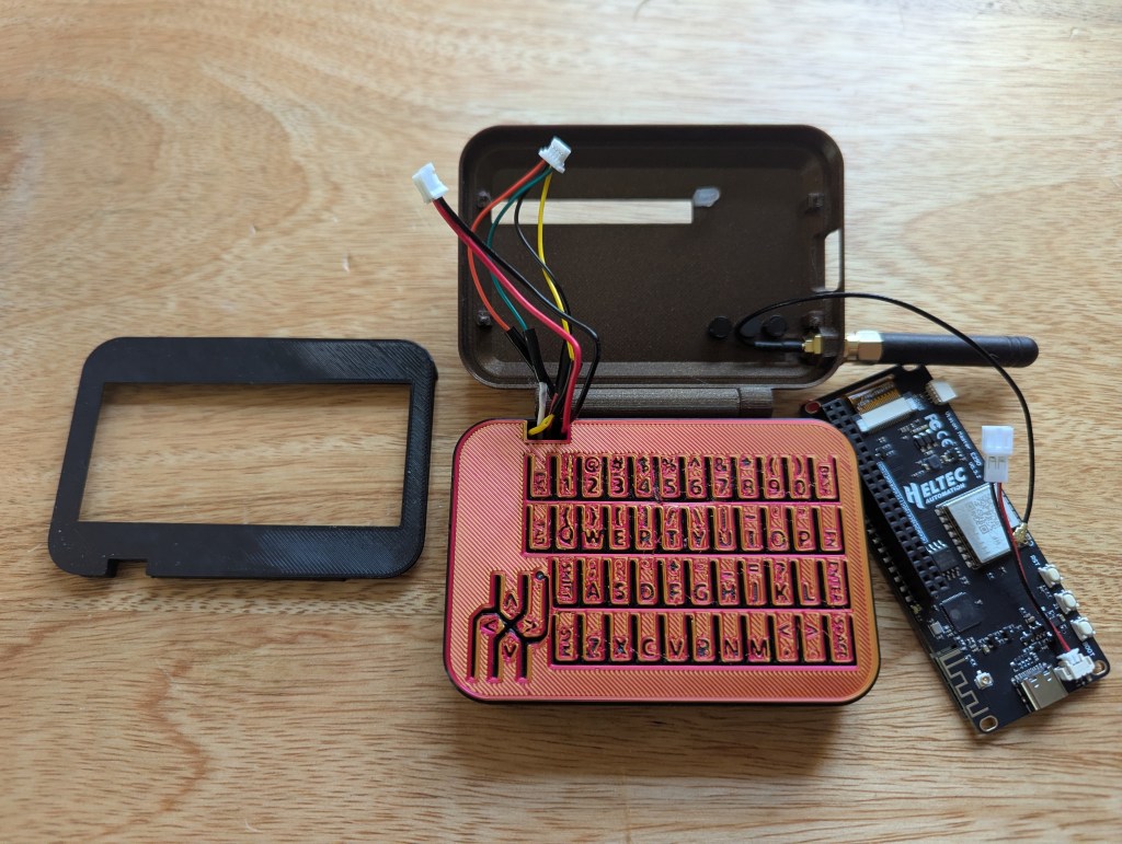
(That keyboard isn’t AI slop, I promise; that’s just how the first layer of the first prototype print came out!)
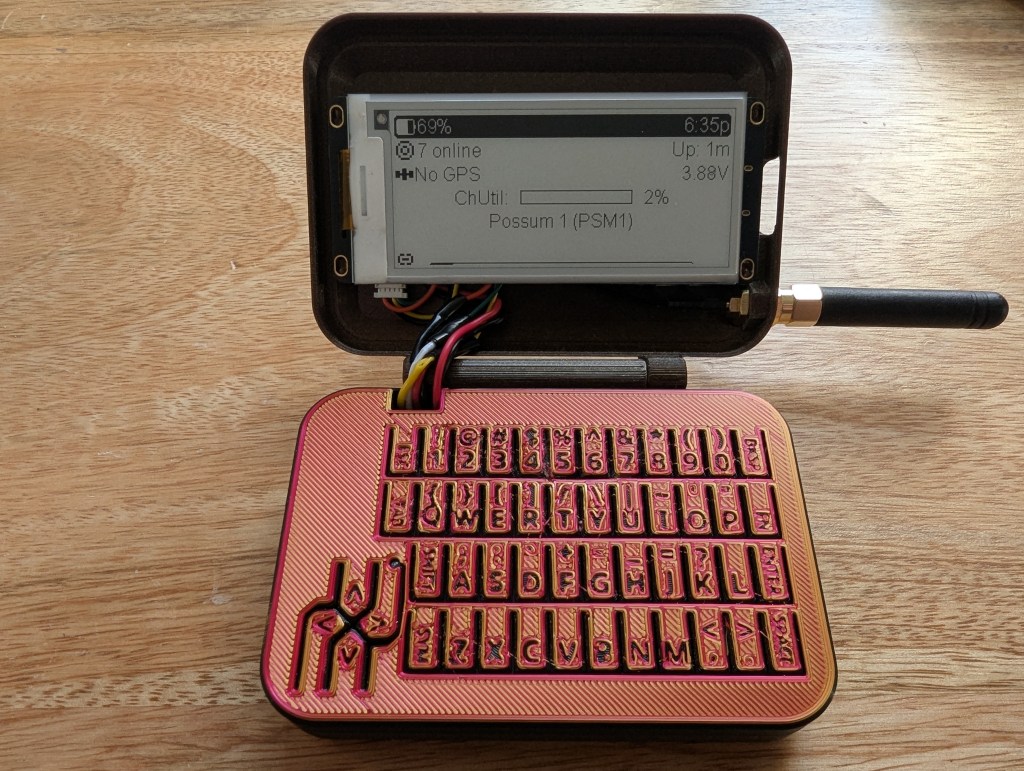
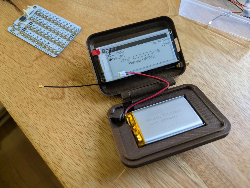
Here’s a case that I put together for some Meshtastic/Meshcore hardware that I had purchased recently. I made the CAD in OnShape over the course of about 7 hours spread across a weekend. I had seen other designs for standalone Mesh messengers (meshengers?) and didn’t like that they had diminutive 1 inch screens and a giant slab of a keyboard/case.
NOTE: this is an early prototype, so check back from time to time as the design evolves!
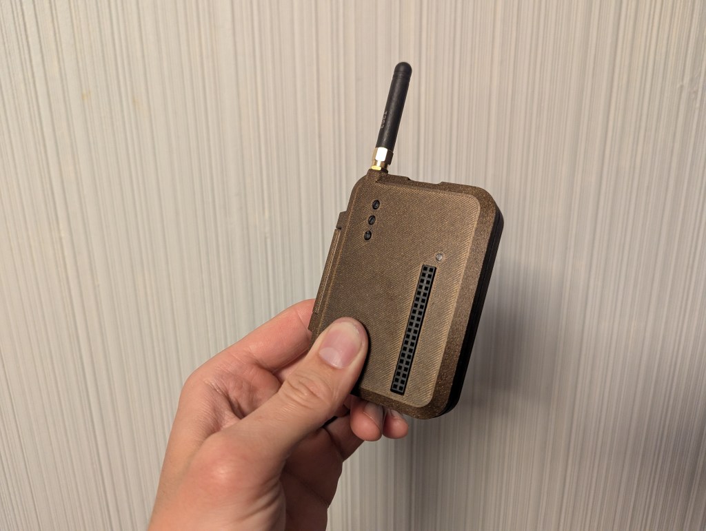
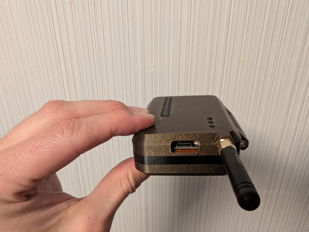
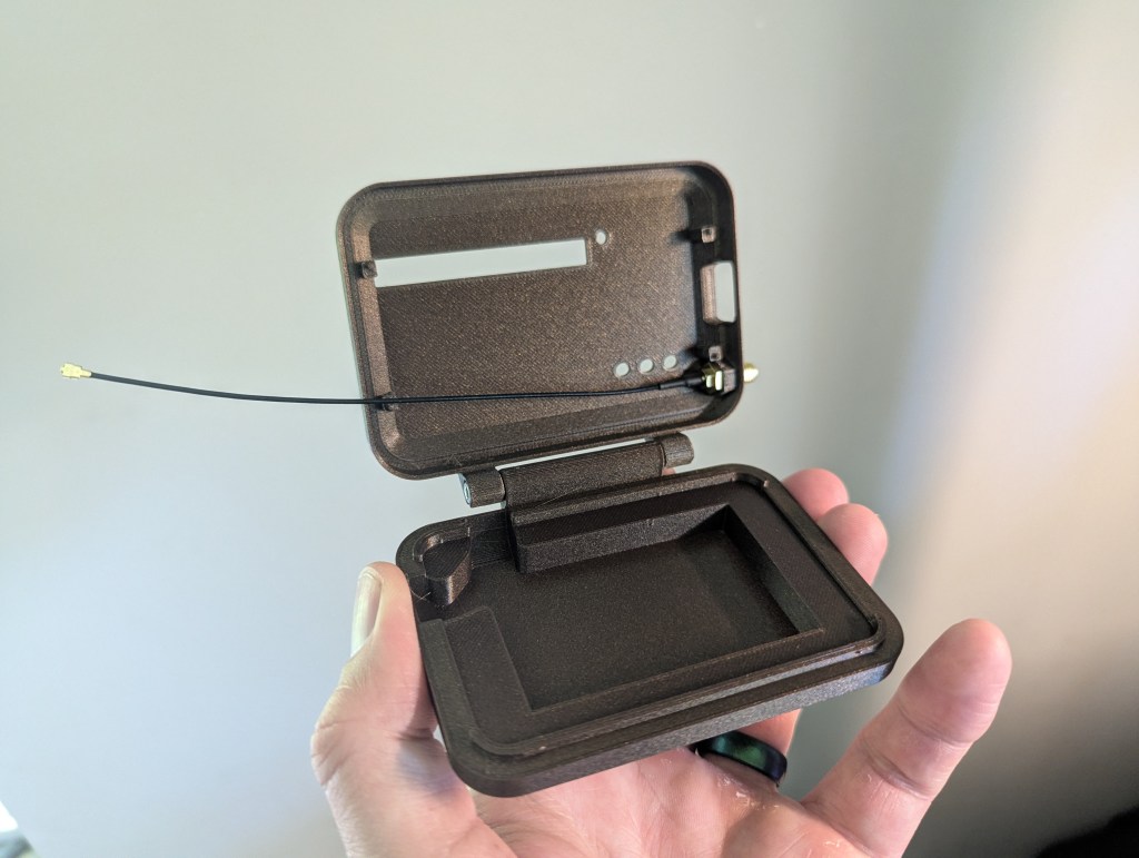
Working around what I have: the board I got included a Raspberry Pi-compatible pin header and 3 buttons on the same side of the board.There will eventually be a flexible cover for the USB port
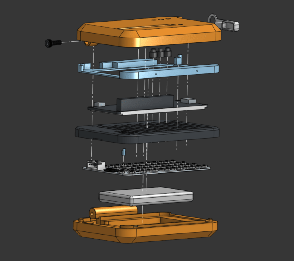
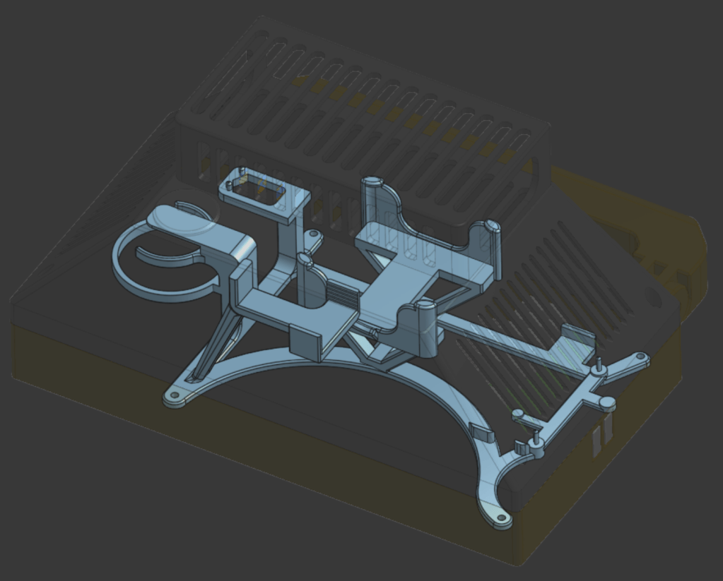
An exploded view of all the pieces of the MeshFlip
I saved some time by finding a model that someone made of the CardKB on GrabCAD. After importing that into OnShape, I made a rough model of my battery, and a slightly-less-rough model of the microcontroller/screen/LoRa radio I got from Heltec. Every other part was derived from those geometries.
I kept the design mostly 3D-printed for ease of production, but I did use a couple of screws for the hinge for added strength. I went with M3’s because they’re so commonly used for build 3D printers (I used 2 that came from the spares bag for my Prusa).
Engineering
One aspect of this that I was curious about was how long my 3D-printed “key caps” might last. I took advantage of the flexibility of polymers to create a keyboard that flexed in order to press the tiny tactile switches on the CardKB. I assumed it would work for a short life, but materials have an interesting property called fatigue, where even if you never stress something past its failure point, bending it back and forth enough times will eventually make it break with much less effort required (you may have inadvertently discovered this if you’ve ever bent a paperclip back and forth until it broke).
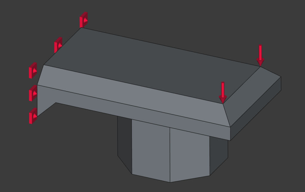
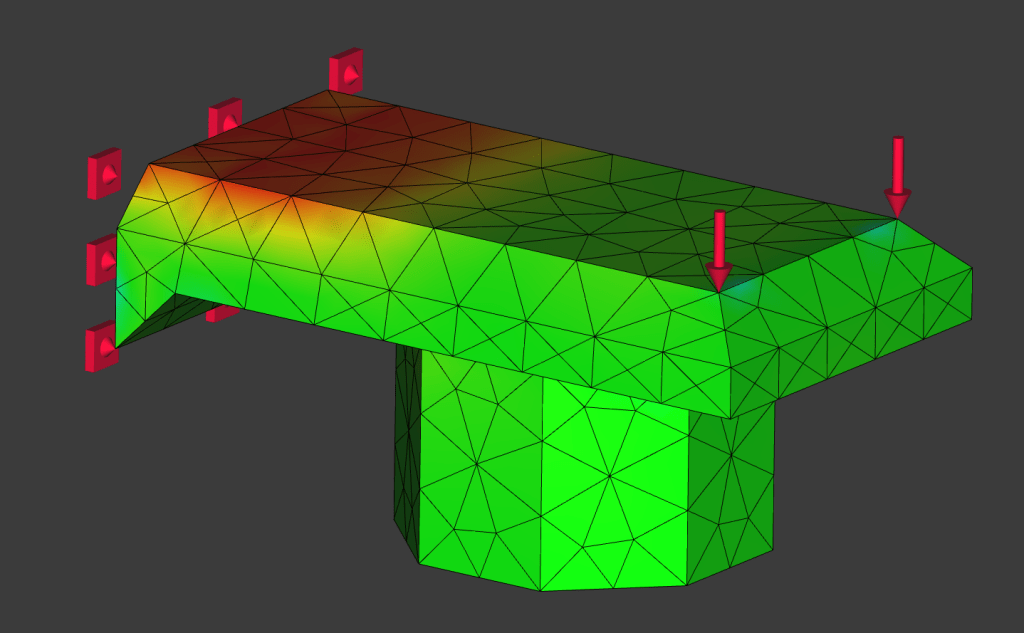
There are many good research papers and reference tables on fatigue life of various materials. I found this one that tested ASA, a UV-resistant polymer that is popular in the 3D-printing community for outdoor applications. For figuring out how my little key caps might do, I modeled one of them in FreeCAD, and used FreeCAD’s FEM workbench to see what the worst stress my part my experience might be.
A rigid constraint where the key cap is connected to the keyboard, and a force pressing downwardThe meshed part with the highest stresses shown in red
Table 5 in the above-linked paper shows that exceeding 25% of the tensile strength of ASA would rapidly start diminishing the number of key presses my keys could handle from a million to the hundreds. My current geometry falls around 35%, which translates to the keys possibly being good for about 50k cycles – not too shabby for a first try. This version was made with parts on hand and 3D printing filament, but I think that future versions will use either a TPU or silicone membrane keyboard, so I won’t spend too much time optimizing this design.
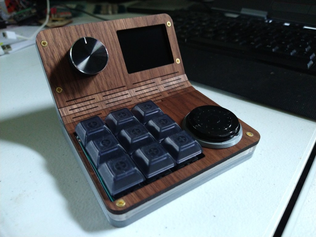
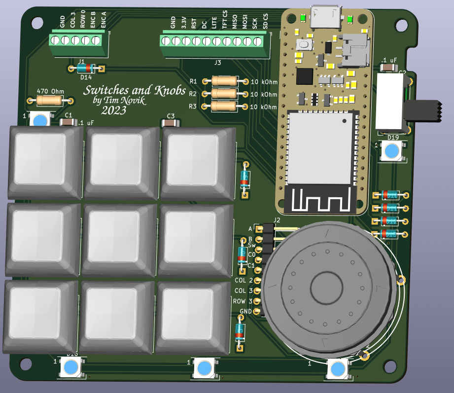
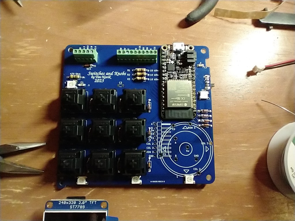
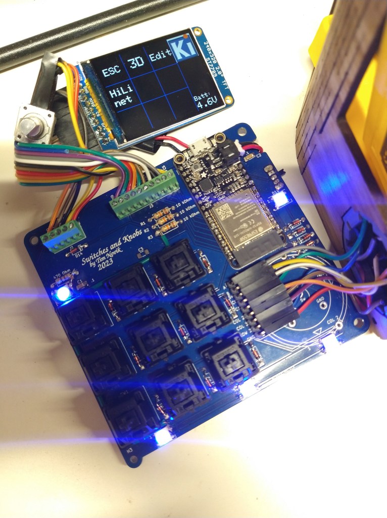
My local makerspace hosted a class where you design and built a macropad, which for those that don’t know is a little programmable keypad that you keep next to your computer. Each key can be assigned a different function, such as raising/lowering volume or performing a multi-key shortcut in a program you use frequently. The design provided by the instructor had 6 keys and a knob, which would provide a decent amount of supplemental functionality, but I wanted to be able to have a group of shortcut keys for each of the programs I use regularly, not be stuck with just one. It took me a while to emerge from the subsequent rabbit hole, but I ended up with a gadget that I was happy to use day-to-day. My computer sees it as a Bluetooth keyboard, so it’s easy to connect and use wirelessly, it has a screen that lets me scroll through presets for different applications, and there are RGB LEDs around the outside to both give it some pizzazz and to give me a visual clue regarding what preset I’m in.
Design
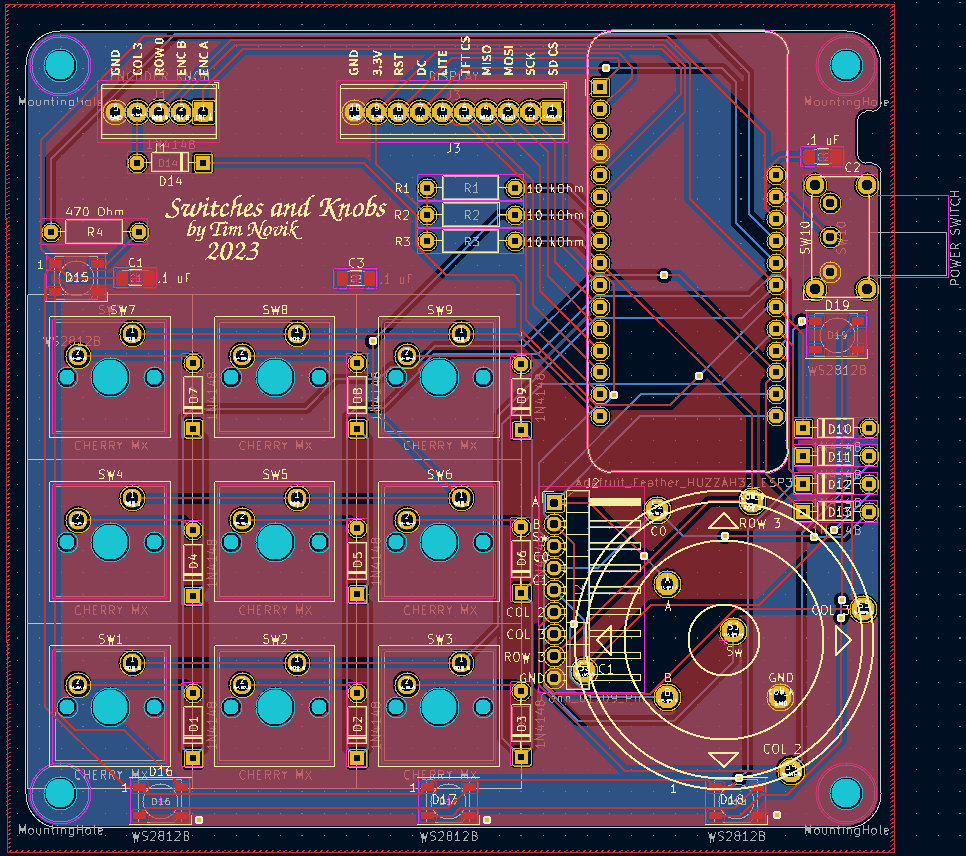
This was the second circuit board I had ever made, with the first one being a simple voltage tester that I made as part of a KiCAD class. KiCAD is a printed circuit board (PCB) design program that’s completely free and open source. One incredibly useful feature is the ability to export a 3D model of a completed PCB, parts and all, making it much easier to design an enclosure around it. I initially started the case design in FreeCAD, but was forced to move to OnShape when the complexity of the model made FreeCAD unable to properly adjust when I made small changes to the assembly.
Hardware
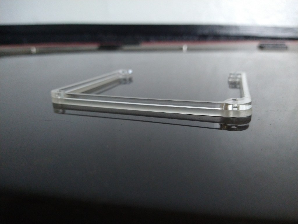
Making the enclosure involved a combination of 3D printing, laser cutting, and woodworking. I wanted to give the device a Star Trek original series look/feel, and I think that between the walnut top and general form factor I got pretty close. I got the walnut to bend by cutting a “living hinge” into it, which is a series of small, parallel cuts that allow the wood to flex just enough to bend into the shape I wanted. Living hinges would fail quickly if subject to cyclic loading (bending back and forth a bunch), but the rest of the case held the walnut fast once it was in position.
The center layer of the case is clear acrylic that I cut into shape using a CO2 laser. I sanded the outside of the acrylic to give the LED lighting a more diffuse look.
Code
Simpler macropads can use a pre-made keyboard firmware, such as QMK, to quickly program their keys. Since my macropad had an entire user interface built in, I had to write my own code. I used Arduino IDE, which allowed me to use many helpful libraries developed by other (such as Adafruit). If I had to start the project over again, I’d probably use either Micro Python or Circuit Python; both make it easy to open the microcontroller’s file system like a thumb drive and paste in new code without needing to recompile it. This is helpful when, for example, I want to add a new set of macros to the device.
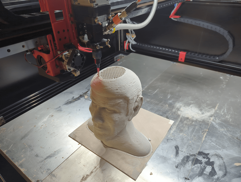
This printer boldly goes where other printers are just starting to go as well.
Overview
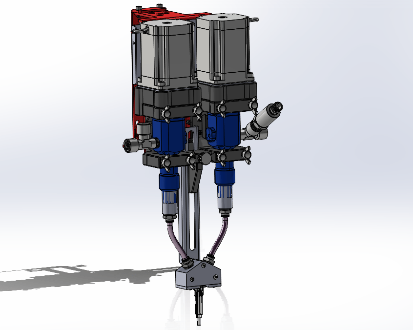
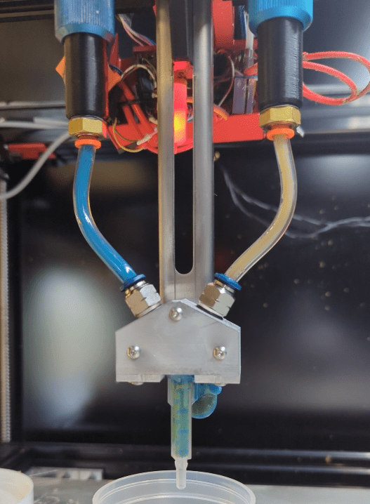
One of my favorite recent (and ongoing) professional projects is the conversion of a large-ish (1 cubic meter build volume) filament 3D printer into a dual-head thermoset printer that can print with any number of goopy materials. One advantage of printing with thermosets is that you can really dial in your material properties while mixing your batches of print media. A little more stiffness or a little less thermal conductivity, for example, can be had by adjusting your recipe at mixing time. One disadvantage, however, is that you need to be able to pump this rather thick material from a cartridge or bucket through a length of tubing out to your extruder. Rather than having a little stepper motor push or pull your filament along, you now have to deal with pressures exceeding several hundred psi.
The university lab (University of Tennessee, Knoxville) that hired me to build this system is made up primarily of students researching how to improve the printing materials themselves. My part to play is to develop and improve the hardware that those materials are printed with. The goal is to make a system that can be used by someone with minimal training and as invisibly as possible. In other words, once someone turns it on, it should take care of itself the entire time the printer is running.
Brainstorming
Laying things out virtually before committing to real hardware
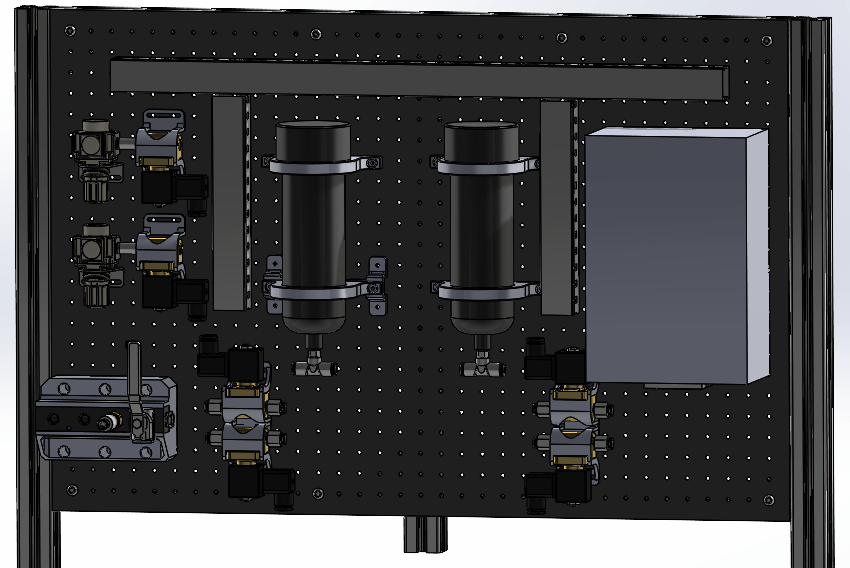
While we were still working out how this type of system might work, good hydraulic design practices suggested that we should include an “accumulator”, which is a bit like a little pressurized storage tank between the pump and extruder that evens out spikes and dips in pressure. Maintaining pressure out to the extruder helps prevent the extruder from running out of material in the middle of a print. A drop in pressure might mean that material isn’t getting out to the extruder fast enough, which can cause gaps in the print, possibly ruining it.
After some initial experimentation, I found out that our print material is so thick that the lab’s 100 psi air pressure wasn’t enough to push material back out of an accumulator after it filled up. This was frustrating at first, but the solution ended up being wonderfully simple: remove the accumulator entirely. I came upon some reinforced flexible tubing that hit a balance between strength and stretchiness that allowed it to handle our pump pressure while at the same time smoothing out material flow, reducing both complexity and cost from the design.
Early design for 2-material printing
Hardware
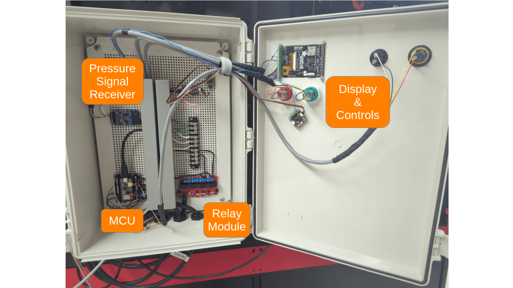
An early version of the control boxBlue + yellow = greenish!
While there are purpose-built industrial pumps for moving materials that vary in thickness from “like honey” to “literally clay”, they have quite a premium price tag. Commodity-grade grease pumps, on the other hand, are capable pushing thick materials while handling pressures upwards of 5000 psi at a much more reasonable price point. They don’t tend to have any sort of controls apart from an air pressure input to cycle the pump, so I came up with my own using an ESP32-based microcontroller and some solenoid valves. The microcontroller keeps an eye on the pressures at the pump and at the extruder, and turns the pump on and off as needed to keep both within a range that keeps the printer going without running out of material. It’s incredible how much code it takes to essentially flip a light switch on and off: I’m at about 800 lines of code (not counting imported libraries). Most of the code is for drawing a user interface on the screen of the control box, with a majority of the rest telling the microcontroller how to read and record pressure data to a microSD card.
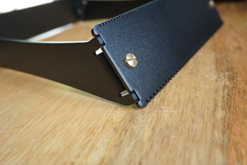
Close-up of how the latest loom design fits together
Overview
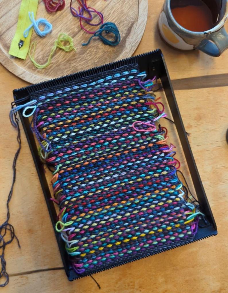
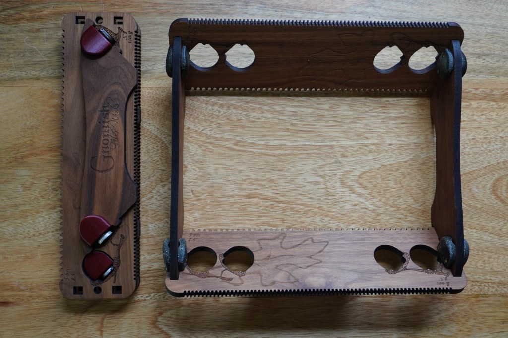
My wife runs a business selling hand-dyed yarn and yarn-related accessories and tools, and every once in a while I do some design work/product development for her. One type of product we’ve been working on is a small weaving loom that can be disassembled and stored in a compact form factor. Originally, we made these out of laser-cut wood boards with 3D-printed connectors.
An early design made from walnut and heat-treatable PLA polymer
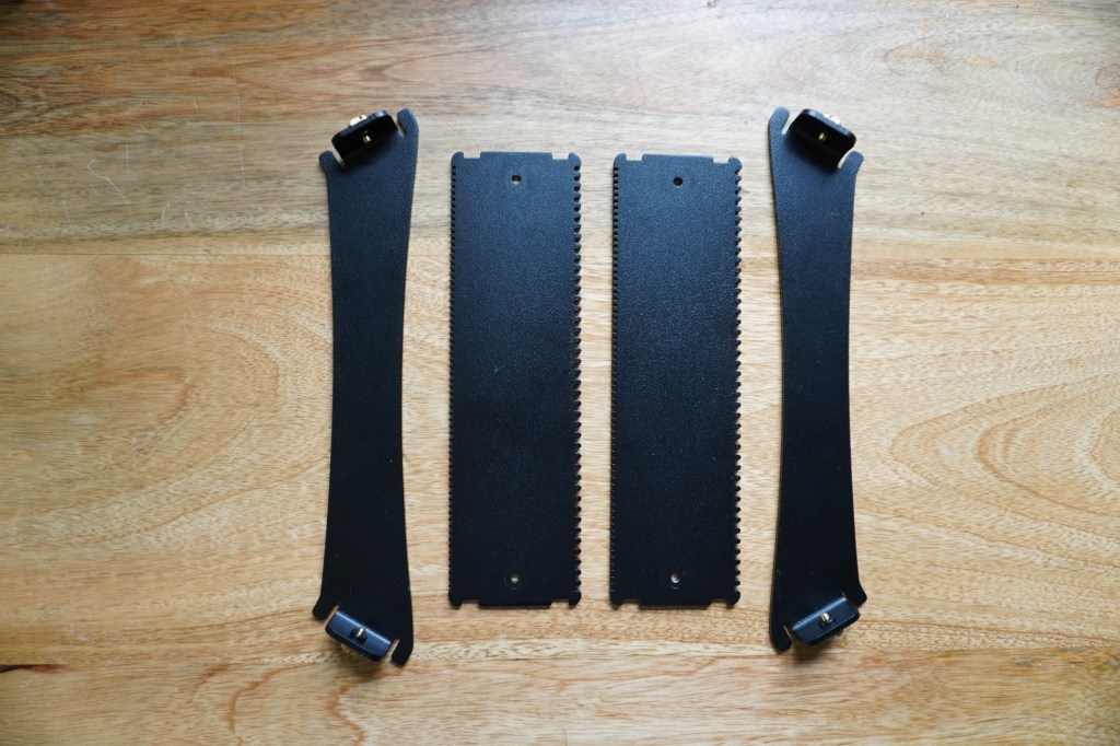
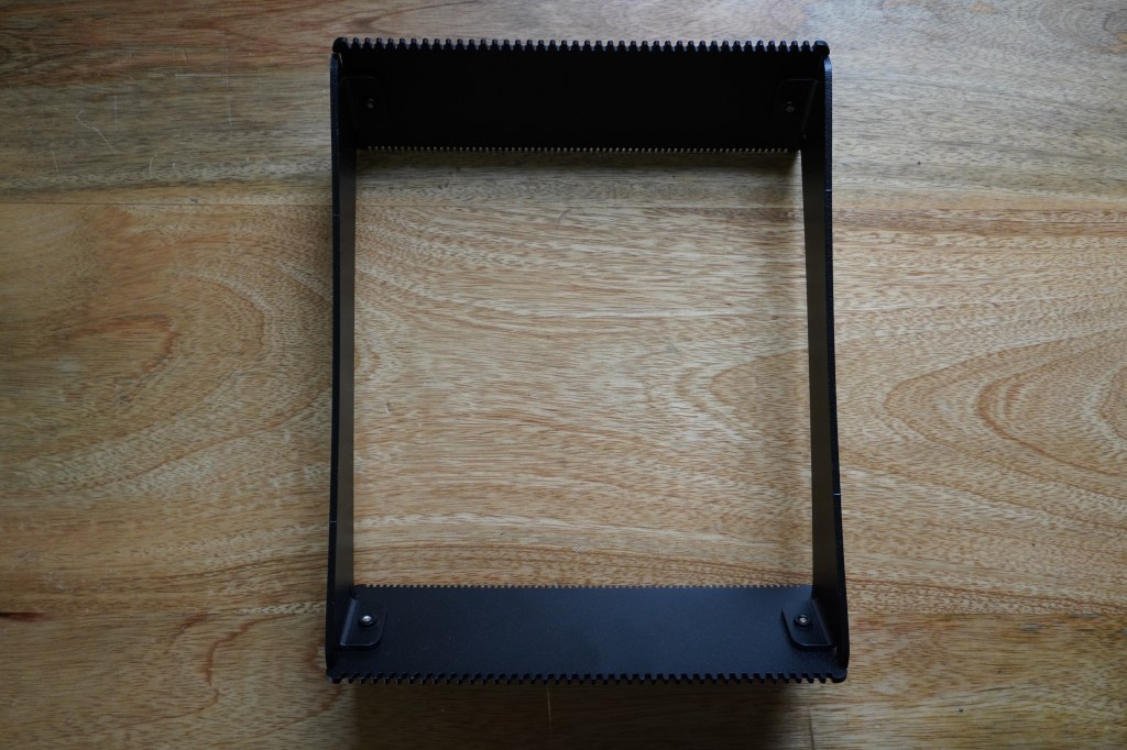
The woodworking and assembly ended up being a bit fussier than we’d like, so I started designing a new version that could be put together with even less manual labor. I made the 3D models in FreeCAD using the sheetmetal workbench. The models were designed in a way that allowed me to create different sizes of looms by changing a single variable in the parameter list. For the material, I chose aluminum with a powder-coated finish to give the looms a combination of decent stiffness, low weight, and corrosion resistance. The plastic connectors were designed out entirely and replaced with bends and press-fit hardware.
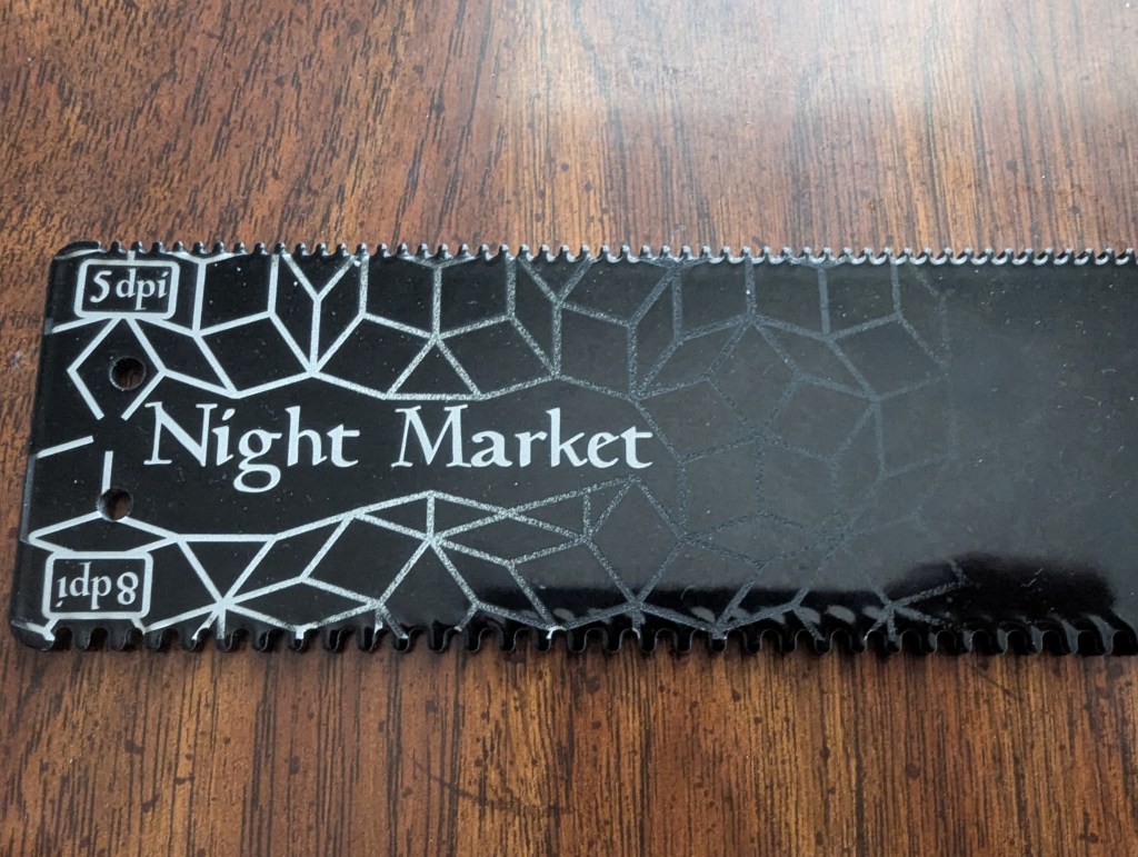
The powder-coated surface lends itself well to engraving with a fiber laser. Shallow passes ablate away only part of the powder-coating, giving the image a subtle look, while cutting all the way down to the aluminum creates areas that contrast the dark powder coating nicely. A dithered gradient allowed me to transition from one to the other while cutting with a single laser power.
A view through the viewport of the fiber laser enclosureAn early prototype metal piece after engraving
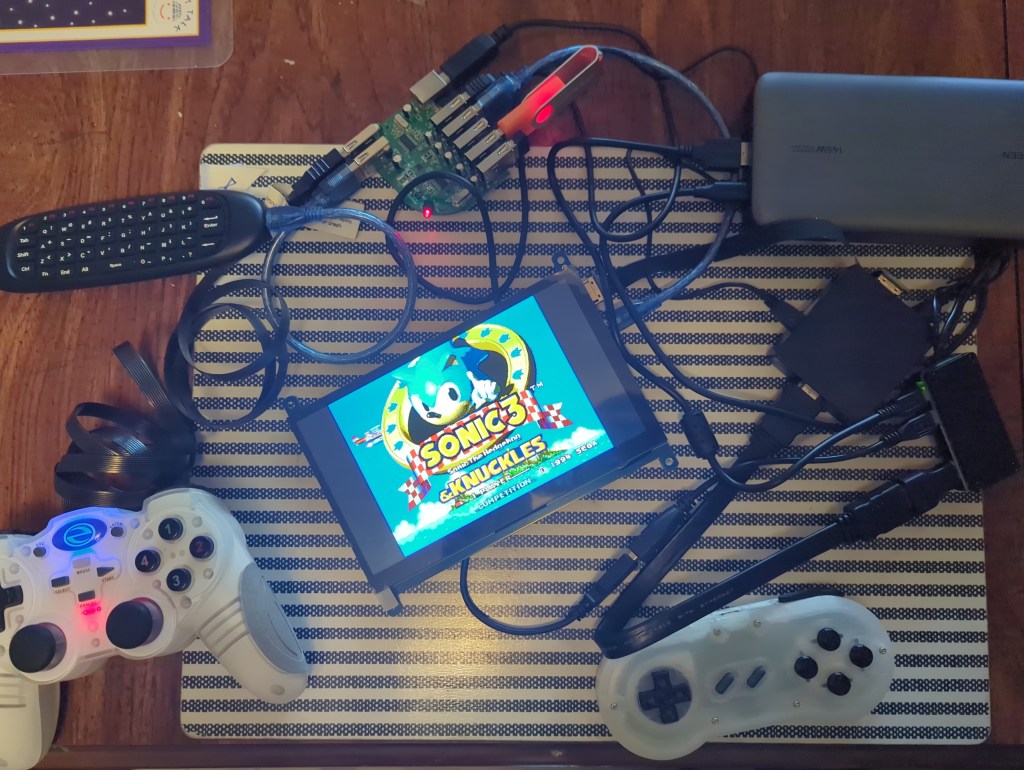
When you make gadgets for work as well as for fun, it’s almost inevitable that you end up with a cornucopia of random parts taking up space in all manner of random bins and boxes. I was overdue for a project that was just for fun, so I decided to see what I could scrape together into a coherent whole. I had recently purchased a Raspberry Pi Zero 2 W in an attempt to make a tiny web-browsing PC out of it, but then found out that the little Pi didn’t even have enough memory to handle a modern web browser. Additionally, the 7″ screen that I bought to accompany it had a resolution of 1024×600, which I had originally thought would be sufficient because many websites seem to be optimized for narrow, vertical viewing. There ended up not being enough resolution — even some apps that came with Raspberry Pi OS struggled to fit into those cozy confines.
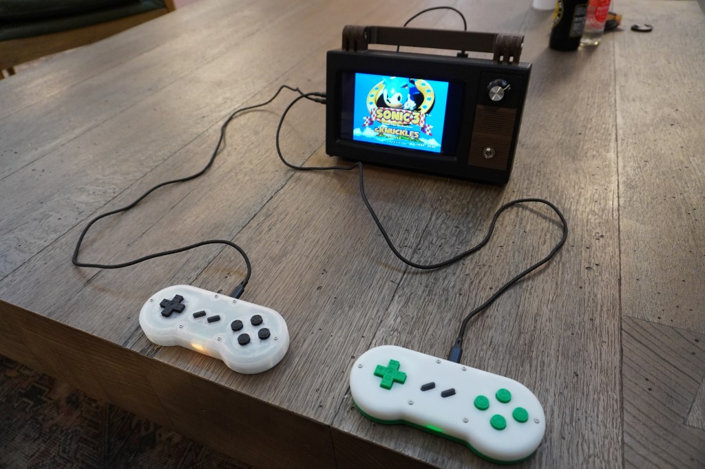
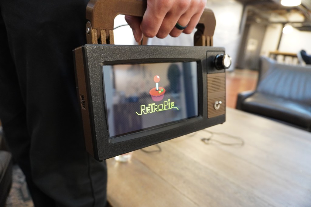
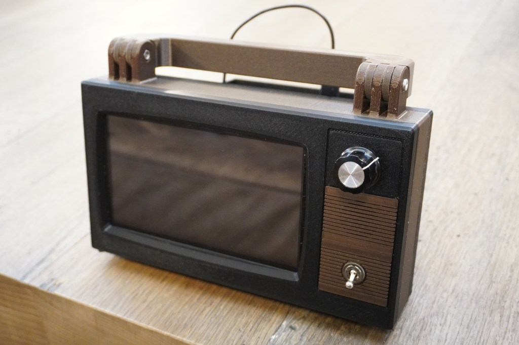
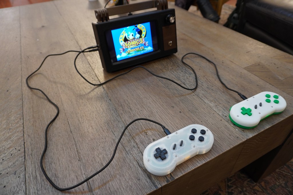
For a while now, I’ve wanted to play some of my classic Sega Genesis and Super Nintendo games with my kids, but I haven’t been brave enough to actually bring out my consoles and leave them at the mercy of curious little hands. One solution would be to simply install some emulators on one of our computers, but that wouldn’t quite capture the magic of sitting in front of a TV with controllers tethered to the console. With enough surplus hardware in hand, I finally had an excuse to design something convenient enough use and relocate on a whim, but that maintained at least a facade of the 16-bit console gaming experience. I call the result the Retrovision Z2W.
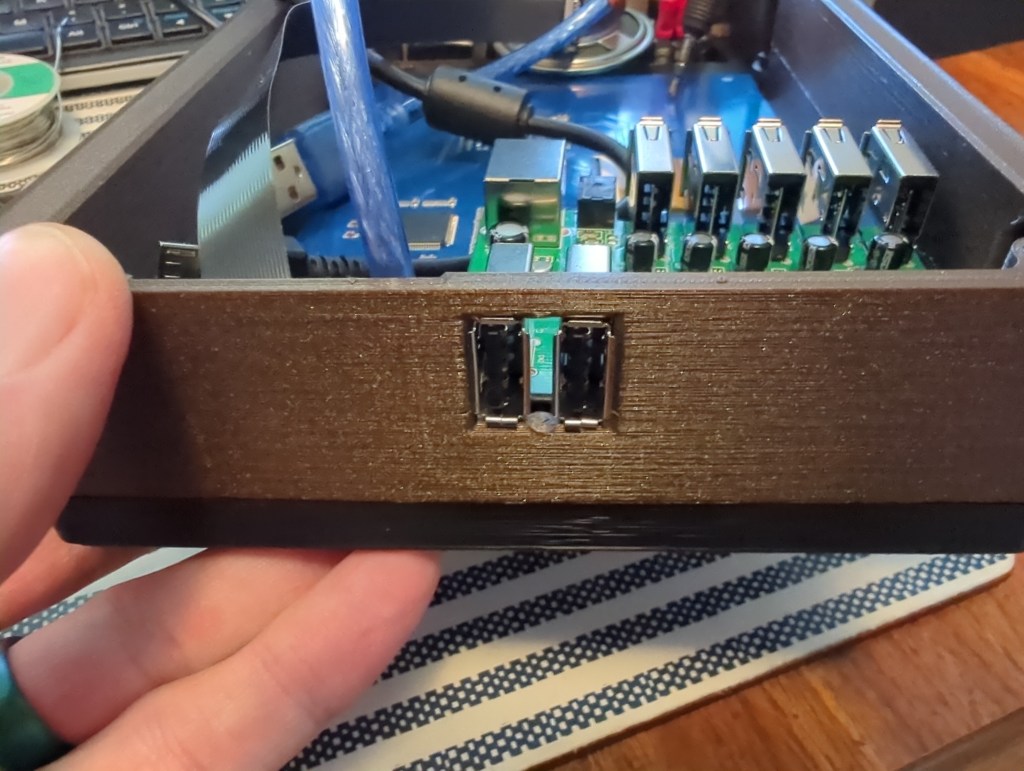
Since this was meant to be a just-for-fun project, I made it a goal to only use pre-made components for the electronics. Between what I had on hand and what I found at my amazing local makerspace’s donation rack, I had almost everything I needed. All I had to do was focus on a 3D printed case to hold everything together.
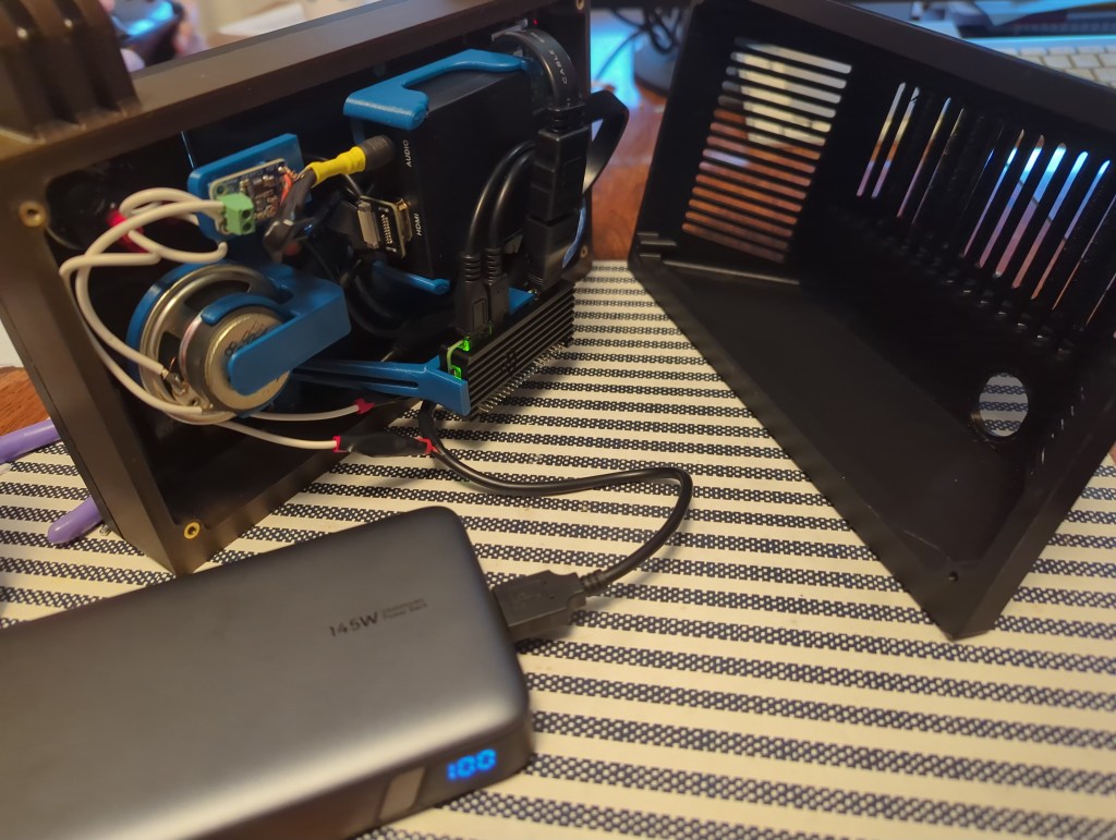
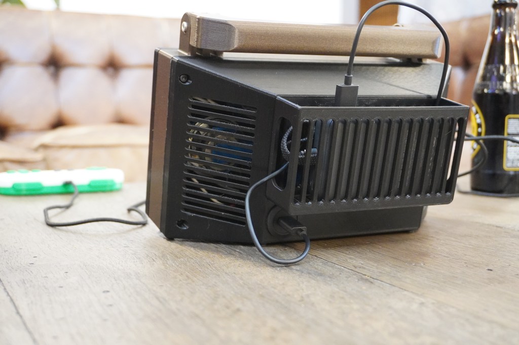
While I originally considered giving the Retrovision a wall plug so that it could only be operated from an AC outlet, I thought that maybe I should stick to the aspects of classic gaming that made it charming and fun rather than adding undue restrictions on its use. In the end, I decided to use a USB-C panel passthrough on the back of the unit so that it could be powered from a power bank, or, if one desires, from a 5V wall wart.
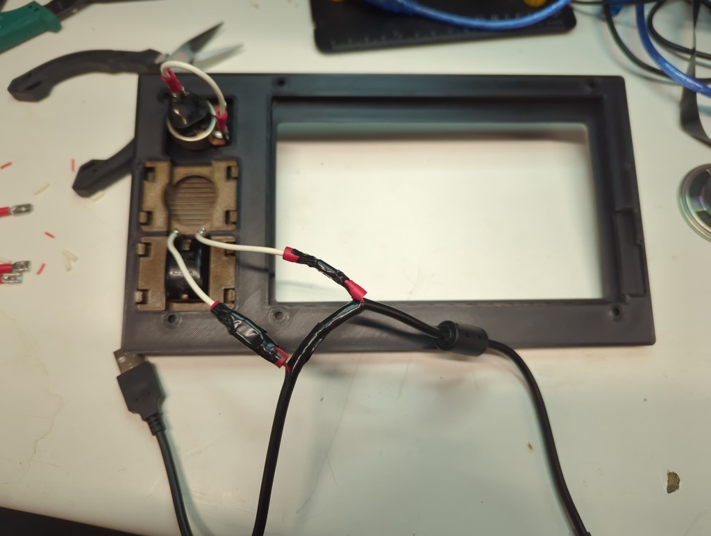
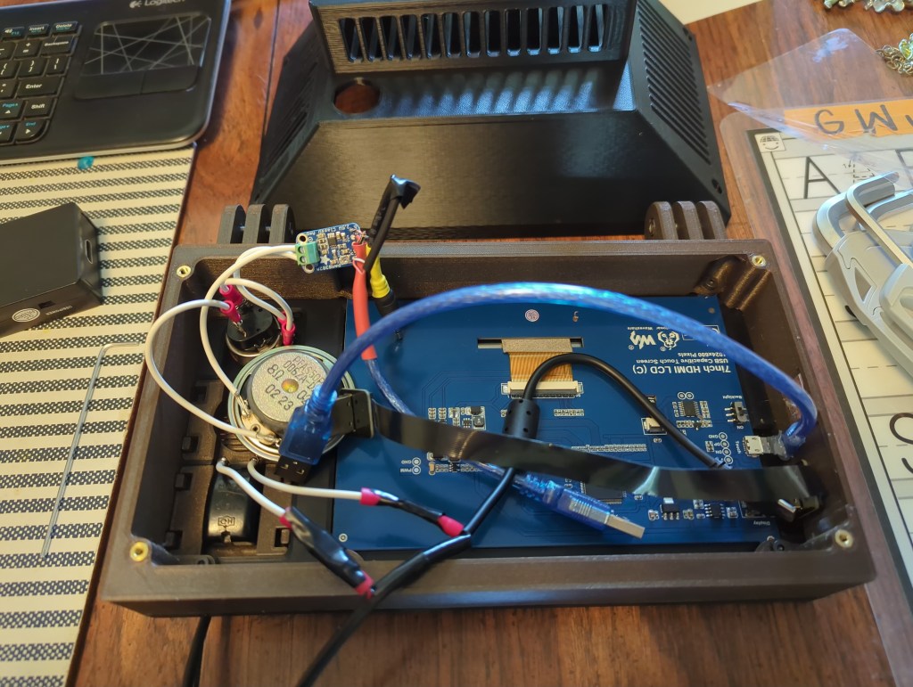
If I was starting this project from scratch, I would have used hardware with an audio output built in. Since I was mostly working with what I had on hand, I had to buy a few extra parts to make the sound work. The screen had an HDMI input but no audio output, so my workaround was to instead feed the HDMI output of the Pi to an HDMI audio extractor. This passed the video to the screen, while giving me an headphone jack to plug my speaker into. Unfortunately, the headphone jack only provided line level output, which is good enough for headphones but not enough to drive anything bigger, so I bought a little audio amp breakout board to rectify that little issue.
CAD Design
As with many projects, I started working on the 3D models for this one in FreeCAD. Unfortunately, as with many projects, I hit a point where the difficulty of working around the quirks of the current FreeCAD user experience pushed me toward another established CAD system. (In this case, rounded corners projected onto to sketch were a nightmare to turn into usable geometry. I hear that V1.1 addresses this issue, which I’m excited about) Previously, my main alternative would be Alibre, but I no longer have any machines running Windows, so I tried out the web-based OnShape to see whether I could finally put Fusion/Alibre/SolidWorks to rest for good. While I don’t prefer for my data to be kept in the proverbial cloud, I do think that OnShape is otherwise a fantastic piece of software. The fact that one can access it from any computer capable of running a modern browser is great for anyone that might not have access to a powerful PC. It may well become my program of choice for professional work.
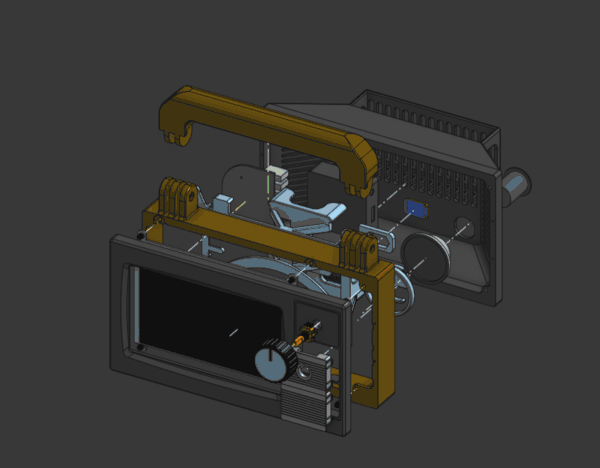
When deciding how large to make my little gaming box, my lower constraint was the size of the screen, and the upper limit was the size of the print bed on my Prusa. Fortunately, printing as wide as possible on my 3D printer gave me just enough room for the screen and some old-timey switches and knobs on the side.
Since I knew that this was going to be carried around the house by little hands, I decided to add a handle to the top of the system that was sturdy enough to withstand some abuse and prominent enough to be the obvious way to pick the thing up. That way it’d be easy to pick it up with one hand while holding a still-connected controller in the other.
I try to make my designs as easy to put together and operate as possible, the fancy term for which is “design for manufacturing“. When designing something, it’s important to think about the tools that you’ll be using to build your gadget/tool/sandwich/etc. In my case, the enclosure was going to be entirely 3D-printed on a desktop FDM machine, so one thing I needed to make sure of was that my parts could either be printed unsupported, or in an orientation that allowed for breakaway support. The exterior of my little CRTish TV lended itself well to this process by and large. Thankfully, I was able to use breakaway supports when necessary. The back of the enclosure needed some happy trees in order to complete its back surface.
Inside the case, I had the option of simply cramming all the electronics into the big empty internal space of my design, but I wanted things to be just a tad more orderly, so I designed a “skeleton” to hold all the electronics in place. This part really took full advantage of the idea that “complexity is free” in 3D printing, and while it was a bit finicky to break off all the supports afterward, it made routing my wiring a whole lot easier, so it was very much worth the time.
Onshape worked well for my preferred CAD workflow, which involves moving all my known parts to their correct places in space and then building whatever else I need directly off of them. If you ever start making CAD models this way, always make sure that all your sketches and assembly joints are fully constrained, otherwise your entire model might accidentally blow up on you in exotic and unexpected ways. It takes less time to shore up a model as you go than it does to be unable to fix a blow-up and have to start from scratch, as I’ve learned over the years.
Iteration
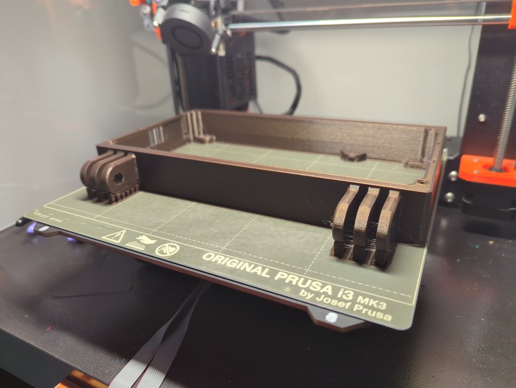
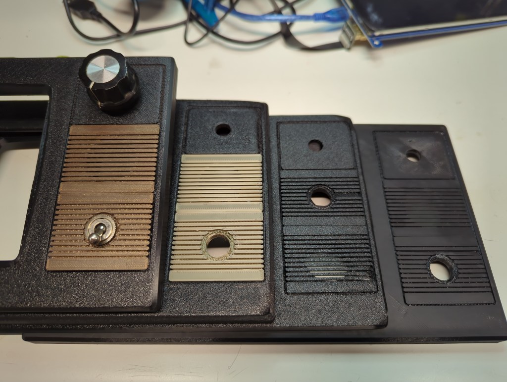
Thankfully, this design came together pretty smoothly. The main thing I iterated on was the look and feel of the front. I switched from a smooth to a textured print bed, and chose the darker of two brown filaments I had on hand. I designed the small brown inserts for the power switch and sound hole to be removable and interchangeable, but the original tabs I drew up proved too weak to be made with FDM, so I made a second design that was more robust. Getting the corners of the front panel not to curl also turned out to be a challenge when I switched to the textured build plate. I increased the bed temperature and closed up the printer enclosure, which didn’t completely resolve the issue, but at least reduced it enough that it almost looked like it was part of the TV-inspired design.
The volume knob went through a few iterations as well; both the knob that you see on the outside and the potentiometer concealed underneath changed from the start of the project to the end. The longer I rummaged in the spare parts bins, the more fantastic candidates I found. in the end, I chose a slightly smaller knob that fit the case better than the giant original one I found, and a potentiometer that had a built-in push-pull switch so that I had the option of muting the system entirely.
Assembly
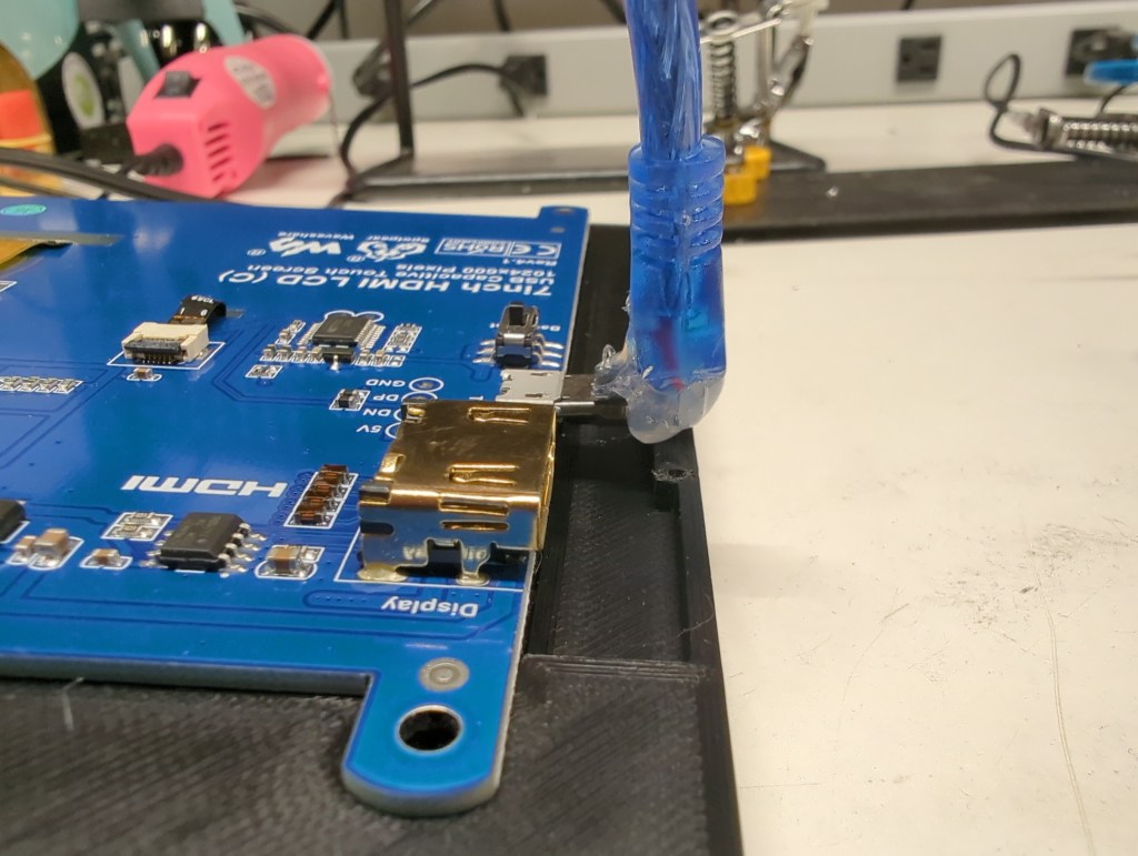
I designed the Retrovision to be assembled from front to rear. That way, I could place the front part of the case face-down on the workbench and assemble the whole unit without needing to reorient it multiple times. I don’t have a special soldering iron tip for installing threaded insert, so instead I rested them on my Pinecil for a few seconds before melting them into place via their pilot holes in the prints. I did have to hack apart a few USB cables: The USB cable providing power for the whole unit had to have a power wire cut so that I could turn the system on with the old toggle switch mounted to the front; The cable providing power and a data connection for touch input to the LCD needed to have its molding cut on one end to squeeze the cable into the tiny amount of space I had available to me between the screen and side of the case; and a third cable had to have one end chopped off so that I could route power from the USB hub to the audio amp. All of these hacks could have been avoided if I was designing this product to be produced commercially from the ground up, but since I was just having fun with (mostly) what I had on hand, getting the wire cutters and spade connectors out was no big deal.
Controllers
I wanted to give my kids a chance to have a stake in making this system, so I looked online hoping to find a controller kit that they could put together. As luck would have it, Handheld Legend sold exactly what I was looking for. I just had to do some light soldering when first receiving the kit, but the kids got to pick out and print their own button and case colors and put it all together. They got to build their first functional electronics, and we all got to play video games together. Win-win.
Software
I installed Retropie. It worked right out of the box. I added my games and was all set. The open source community is a truly indispensable asset to all makers.
Thoughts
Overall, I’m thrilled with how this project turned out. Between finding a purpose for parts that might otherwise end up collecting dust indefinitely and incorporating scavenged old switches for a proper tactile experience when turning the system on or adjusting the volume, this little system is just what I was hoping to get out of the experience. The resolution of the screen is just fine for displaying old games, and the single speaker I saved from the trash can sounds exactly as good as it looks like it should.
Would I send this design off for mass production? Nah. If that was the plan, I’d start fresh and remove the vast majority of the internal wiring that this one required. That was never the intent here, though. I got to turn some assorted stuff into something that will hopefully create some fun memories for my kids and me.
Welcome to my blog! I want use it to share information about the gadgets that I make both in my professional and personal lives. As many projects as possible will be open source so that I can contribute back to the worldwide community that has enabled both my hobby and profession.
My name is Tim and I’ve always been interested in how things are made. As a kid, I took apart my fair share of appliances to see their inner workings, and eventually got better at putting them back together. While I went to school for mechanical engineering, I’ve also learned a great deal about electronics and microcontrollers – I wanted to be able to design, build, and modify every aspect of the gadgets I come up with.
When I’m not designing some circuit board or mechanism, I enjoy spending time outdoors with my family, whether we’re hiking, biking, or just hanging out and enjoying each other’s company.